


Quick Start Guide
Speco Technologies DVR-4TH/8TH/16TH
®
Customer Service: 1-800-645-5516
200 New Highway, Amityvile, NY 11701
www.specotech.com
READ THIS FIRST!
This document is intended to serve as a quick reference page for
initial set-up. It is recommended that the user read the entire
instruction manual before beginning. Basic programming can be
accomplished by simply reading the appropriate instructions first,
then scroll through the easy to operate “On Screen Display” and
make changes.
Please note that the Accessory Kit and Shipping Box contain
the following items:
z 1 – Quick Set-up Guide
z 1 – Digital Video Recorder
z 1 – User’s Manual
z 1 – Power Cord
z 1 – IR Controller
z 2 – Rack mount ears
z 1 – CD-Rom (includes manuals, HDD storage calculator and
player software)
Preset Accounts (username, password):
Account 1: admin, 1234
Account 2: user, 4321
Use the same accounts to login local DVR and SpecoRemote™.
The following list represents features that most users will need to
be familiar with. Please review the list and refer to the specific
pages listed in the manual. Please read the appropriate section of
the manual thoroughly and perform the function on the DVR
before attempting to contact technical support.
Please note that numbers 1 & 2 MUST be performed before
making your first reading.
Please refer to configuration section of User Manual.
1 Set Time/Date:
2 Format HDD
3 Schedule Recording
4 Motion Detect Recording
5 Optimize Record Time/ FPS settings
6 Network & Internet Setup
7 Playback
8 Video Backup
Do not block the fan on the unit –
enough airflow is needed to
protect the unit from over heating.
Front Panel & Functions
The unit’s front panel controls enable the user to control the unit and preset
programmable functions.
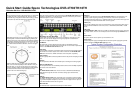
LED Definition
The DVR-4TH/8TH/16TH Series LEDs on the front panel are described as follows:
Power LED (Green)
The LED should be lit when the power is connected.
HDD LED (Green)
The LED should be lit while the HDD is processing data.
Alarm LED (Red)
The LED should be lit when an alarm is triggered.
Network LED (Green)
The LED should be lit when the DVR-4TH/8TH/16TH series unit is connected to a
network and blink when any data is being transferred.
REC LED (Red)
The LED should blink while the DVR-4TH/8TH/16TH series unit is recording.
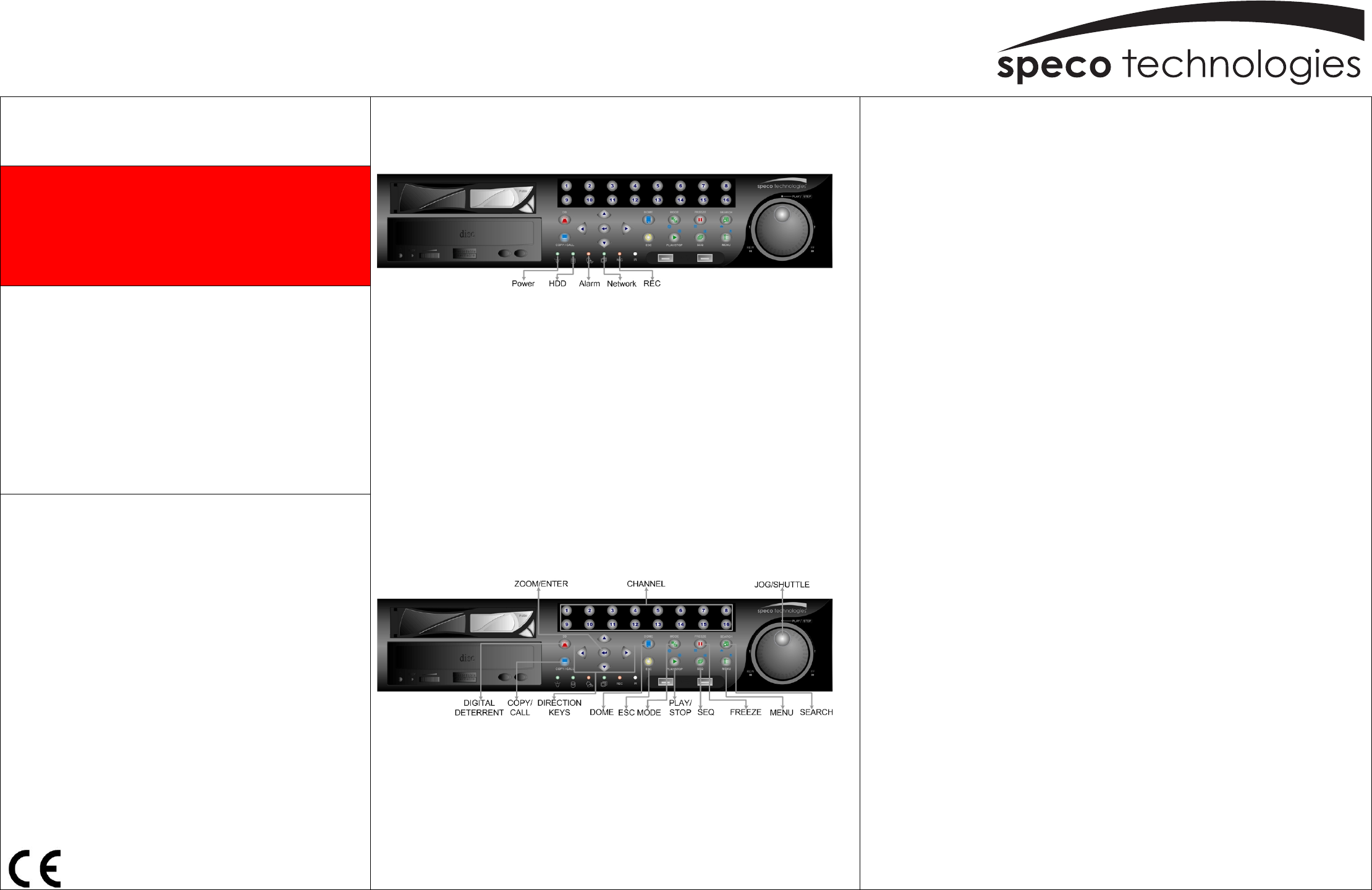
Function Keys
The DVR-4TH/8TH/16TH series unit function keys on the front panel are described to
the right for normal operation.
JOG SHUTTLE: Operation instruction on back page.
D.D.
Users can trigger warning announcement at certain camera site by pressing the specific
camera key and the digital deterrent key.
CALL/COPY
Press to enter Call Monitor Control mode. This is also used to quick export video to an
external devices, including USB DVR+RW and ThumbDrive, etc.
Direction Keys
* In Zoom mode, these keys function as Direction Keys.
* In the OSD setup menu, the Direction keys are used to move the cursor to previous or
next fields. To change the value in the selected field, press UP / DOWN keys.
DOME
Press this key to enter Dome Control mode.
ESC
Press to cancel or exit from certain mode or OSD setup menu without changing the settings.
MODE
Press repeatedly to select desired main monitor display format. There are four viewing
modes available: full screen, 4-window (2×2), 9-window (3×3), and 16-window (4×4).
PLAY/STOP
Press this key to switch between live image and playback video.
FREEZE
• Press FREEZE while viewing live image, the live image will be frozen, but the date/ time
information shown on the monitor will continue updating. The recording of the video will
continue as well. Press FREEZE again to return to live mode.
• Press FREEZE while playing recorded video, the playback video will be paused. Press
LEFT/ RIGHT to move the recorded video reverse/ forward by a single step. Press
FREEZE again to continue playing video.
SEQ(Sequence)
Press to start automatic sequencing of the video coming in from the installed cameras.
SEARCH
In both Playback and Live mode, press SEARCH to access the Search menu to search and
playback recorded video by date/ time, events, or text.
MENU
Press this key to access the OSD setup menu.
ZOOM/ENTER
• In OSD menu or selection interface, press this key to make selection or to save settings.
• In live full screen viewing mode, press to view a 2× zoom image. Press it again to return.
CHANNEL
• In both Live and Playback modes, press any CHANNEL key to view the corresponding
video in full screen. The number of the CHANNEL keys corresponds to the number of
cameras supported by the unit.
• In Dome Control mode, the key “1” is used to access the Set/ Go Preset menu while the
key “2” is used to hide or display the dome camera setting parameters.