


– 8 –
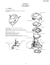
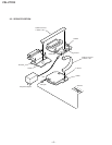
FDL-PT222
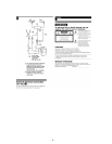
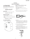
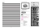
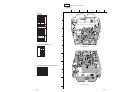
[COLOR PHASE (TINT) ADJUSTMENT (RV301)]
1. Receive the color bar signal from the signal generator.
2. Observe the waveform across JL81(B) and JL67(D.GND).
3. Adjust RV301 (TINT) so that the waveform level becomes as
shown in Fig. 3-6.
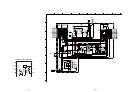
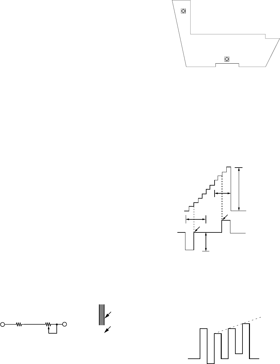
[CONTRAST ADJUSTMENT (RV402)]
1. Receive the stepped waveform signal in 10 steps.
2. Observe the waveform across JL83(G) and JL67(GND).
3. Check the contrast changes by turning RV402.
4. Connect an oscilloscope between JL84 (AUTO CB) and JL67
(D. GND) and adjust RV402 so that the voltage of A portion
becomes 2.2+-0.2V.
5. Check the waveform as shown in Fig. 3-5.
6. At the same time, check the points C and D are within the
period as shown in Fig. 3-5.
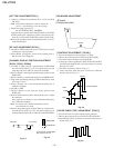
[RF. AGC ADJUSTMENT (RV201)]
1. Set S601 to VHF position and receive a VHF color bar signal
issued from a signal generator.
2. Adjust RV201 and align the screen for the optimal point so
that the snow noise disappears.
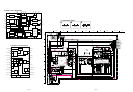
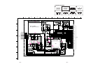
[CHANNEL DISPLAY POSITION ADJUSTMENT
(RV001, RV002, RV004)]
1. Set S601 to VHF position, a potentiometer (47kΩ±15kΩ)
across JL25(CS) and JL77 (+4.5 V) as shown in Fig. 2-6 and
short the points JL21(CH CAL) and JL30 (D.GND).
2. Receive channel 2 and align the channel display positions with
RV002(VP).
3. Receive channel 13 and align the display bar with RV004(VA).
4. Align while performing tracking to mutual interference in the
above steps 2 and 3.
5. Receive channels 3 & 4 and confirm that the display bar is
within the standards.
6. Set S601 to UHF.
7. Receive channel 14 and align the display position with
RV001(UP).
8. Receive channel 69 and confirm that the display bar is within
the standards.
Once again receive channel 14 and confirm that the display
bar is within the standards.
Note : Use caution since shifting channel 69 will also
cause channel 14 to shift.
9. Remove the potentiometer (47kΩ+15kΩ) you connected be-
tween JL25(CS) and JL77(+4.5V). Also remove the short you
connected between points JL21 (CH CAL)and JL30(D.GND).
[AFT FINE ADJUSTMENT(T201)]
1. Connect a 1 kilohm resistor between JL77 (+4.5V) and JL28
(RF AGC).
Note : Perform this adjustment as the last step in the
process since drift may occur due to aging.
2. Switch the sweep signal to CW.
fo= 45.75 MHz±5 kHz, -30±5dBm
Apply the above signal between JL26 (IF) and JL27 (IF GND)
and then make a fine adjustment of T201 so that the level be-
tween JL31 (AFT) and JL30 (D.GND) reaches2.2V±0.4VDC.
3. Remove the 1 kilohm resistor connected between JL77 (+4.5V)
and JL28 (RF AGC).
JL83
JL84
0 IRE
100 IRE
C
D
A=2.2
±
0.2VDC
Contrast changes
Fig. 3-5
Fig. 3-6
Fig. 3-4
Display bar
Channel No.
6
*Channel No. and display
bar are to be in line.
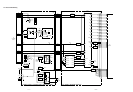
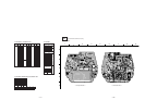
3-3.B BOARD ADJUSTMENT
RV402
RV301
- B board -
(Component side)
JL25 (CS)
JL77(+4.5V)
15kΩ
VR(47kΩ)
Fig. 3-3