


51
15 TROUBLESHOOTING
OPERATION NOTICES
The transceiver has been designed and engineered
to avoid possible hardware glitches. However, you
may notice the following symptoms when you operate
the transceiver. These symptoms are not
malfunctions.
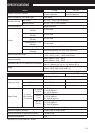
OPERATING VOLTAGE
As stated in “SPECIFICATIONS” {page 53}, this
transceiver operates on a DC voltage from 5.5 V ~
7.5 V DC (battery terminal) or 12.0 V ~ 16.0 V DC
(DC IN jack). If you find that the transceiver cannot
be switched ON, or “VOLTAGE ERROR” appears, the
supplied power source may be outside of the
specified range.
In such a case, remove the DC power cable from the
transceiver immediately and confirm that the supplied
voltage is within the specified range.
TUNING IN SSB/ CW MODE
The transceiver uses a general purpose IF filter to
receive signals in LSB, USB, CW and AM modes.
So, when you receive signals in LSB or USB mode,
the opposite side band signal is not fully attenuated.
At the same time, since the same filter is used for CW
reception, you may have difficulties seperating the
CW signal from other signals in the crowded band.
To best tune in to a SSB signal, follow the instruction
below.
When you receive signals in USB mode:
1 Turn the Fine Tuning function ON {page 35}.
2 Tune to the target signal while starting at a lower
frequency, using the Tuning control.
When you receive signals in LSB mode:
1 Turn the Fine Tuning function ON {page 35}.
2 Tune to the target signal while starting at a higher
frequency, using the Tuning control.
RECEIVING IN AM BAND
If you receive a weak signal in AM band, you may
notice a high pitched squealing noise in the
background. This noise is generated by the internal
DC/DC converter and it cannot be removed.
RECEIVING SIGNALS IN CITIES
When you receive signals in cities, the receiver’s
entire S-meter may light up without receiving any
strong signals. This happens when the RF amplifier
in the receiver is overloaded by strong interference
signals that are nearby. In this case, turn the
Attenuator function ON {page 36} to reduce the
interference signal level. You may further have to
adjust the volume level while receiving the target
signal.
VISUAL SCAN
When you have the same 2 m, 1.25 m (TH-F6A
only), and 70 cm band frequencies for both A and
B-band receivers, the Visual Scan may indicate the
signals on the bar-graph display even if no signal is
monitored on the A-band receiver. This error occurs
due to the internal spurious harmonics that are
generated by the B-band-receiver. Refer to
“INTERNAL BEATS” {below} for the frequencies.
TRANSMISSION
If you continuously transmit for more than 3 minutes
at high power (5 W), the transceiver becomes warm.
If you continue or repeat the transmission before the
transceiver cools down, the thermal protector
automatically decreases the output power to 0.5 W.
“H” also blinks at the same time. If this happens, let
the transceiver cool down for a while before
transmitting again.
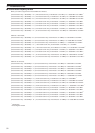
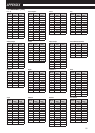
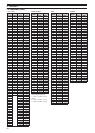
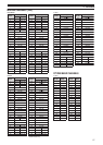
INTERNAL BEATS
If one of the formulas on the next page is true, the
S-meter moves without receiving any signals or you
cannot receive any signals. This is inevitable when
you use superheterodyne receivers.