


45
INTERFACING TO PERIPHERALS
SP/MIC JACK
The SP/MIC jack on the transceiver can be
configured to interface to various kind of the
peripherals available for the transceiver, such as a
speaker microphone (SMC-32/ 33/ 34), PC interface
cable and a TNC. Access Menu No. 9 (SP/MIC
JACK) and select the peripheral type from “SP/MIC”,
“TNC”, and “PC”.
You can further configure the transceiver to interface
to a high speed (9600 bps) TNC that requires a direct
FM modulation {below}.
SELECTING SP/MIC JACK FUNCTION
Unless you connect the transceiver to a TNC or PC,
the default setting of the SP/MIC jack function (Menu
No. 9), “SP/MIC” works fine. However, if you want to
interface to a different type of peripheral, configure
the SP/MIC jack function:
1 Press [MNU] to enter Menu mode.
2 Turn the Tuning control or press [ ]/ [ ] to select
Menu No. 9 (SP/MIC JACK).
3 Press [ ] or [MNU].
4 Turn the Tuning control or press [ ]/ [ ] to select
the appropriate peripheral type from “SP/MIC”
(default), “TNC”, and “PC”.
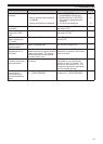
CIM/PS
noitcnuF
epyTlarehpireP
CIM/PS
,tesdaeh,enohorcimrekaepS
hcleuqsatuohtiwCNT,enohprae
troppussutats
CNTtroppussutatshcleuqsahtiwCNT
CP
lortnoclennahcyromemehthtiwCP
reviecsnartehtroferawtfos
5 Press [ ] or [MNU] to store the setting.
Otherwise, press [ ] or [PTT] to cancel.
• If necessary, configure and select the
additional settings.
6 Press [ ] (POWER) to turn the transceiver OFF.
7 Connect a peripheral to the SP/MIC jack.
8 Press [ ] (POWER) to turn the transceiver ON.
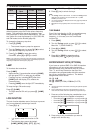
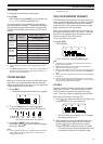
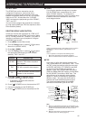
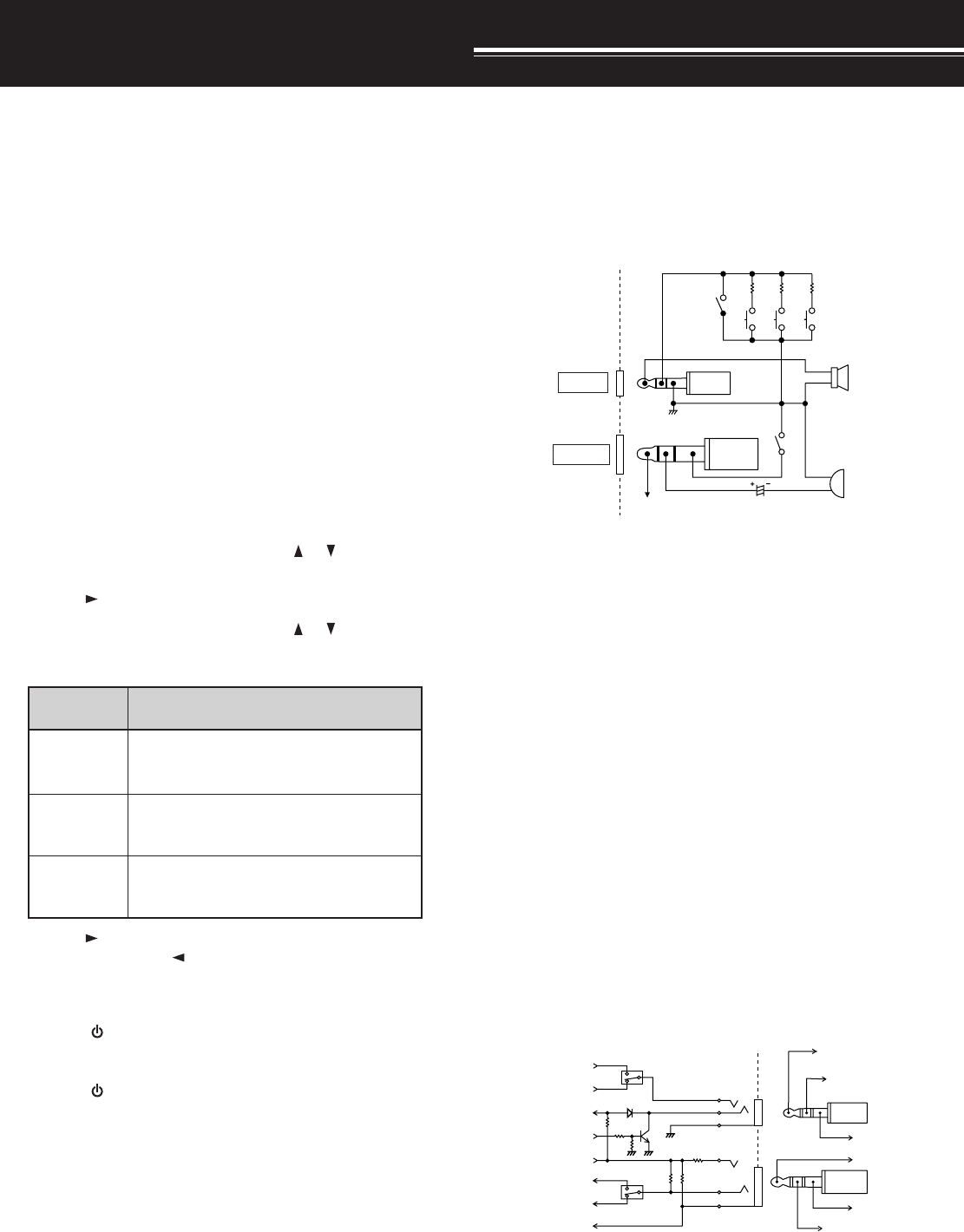
■ SP/MIC
If you plug the speaker microphone or headset
into the SP/MIC jack, access Menu No. 9 and
select “SP/MIC” (default). To configure the
programmable function keys from an external keys
in order to control the transceiver, refer to the
circuit diagram below.
3.5 V
10 µF
PTT
LOCK SW
SW-1 3.9k
SW-2 10k
SW-3 27k
TH-F6A/ TH-F7E
SP
MIC
Note 1:
Voltage is developed across a 100
Ω
resistor on the 3.5 V line in
the transceiver. When 2 mA flows, approximately 3.3 V is
developed.
Note 2:
A 10
µ
F capacitor is not required in the following cases.
•
When other equipment has DC blocking capacitors.
•
When a 2-terminal electret condenser microphone is used.
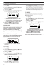
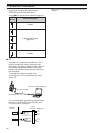
■ TNC
If you want to utilize the squelch status on your
TNC, access Menu No. 9 and select “TNC”. From
the TNC, make the interface cable that connects
to SP/PRD, MIC/PKD, PTT, REM/SQ, and GND
on the transceiver SP/MIC jack terminal. In
addition, if your TNC supports 9600 bps packet
(G3RUH/ GMSK 9600 bps modem), access Menu
No. 28 (PACKET) and select “9600” bps. This
option allows you to transmit/ receive packet
signals in a direct FM modulation/ quadrature
detector output. You must use the A-band to
transmit and receive 9600 bps packet signal.
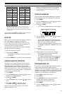
The following diagram shows the available
terminals on the SP/MIC jack for the TNC.
To TNC RX
audio input
To TNC
DCD input
GND
NC
To TNC TX
audio output
PTT
Demodulator output
Modulation input
Speaker output
Remote input
Squelch output
Microphone input
PTT input
3.5 V DC
High speed
(9600 bps)
High speed
(9600 bps)
Normal
(1200 bps)
Normal
(1200 bps)
SP/PRD
REM/SQ
3.5 V
MIC/PKD
PTT
Note:
◆
When you select 9600 bps for Menu No. 28 (PACKET), you
cannot monitor the sound from the speaker. Select 1200 bps
for Menu No. 28 (PACKET) when you return to normal
operation.
◆
While the VOX function is turned ON, Menu No. 28
(PACKET) returns to 1200 bps {page 41}.
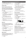
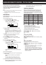
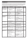
2.5 mm
Plug
3.5 mm
Plug
Speaker
Microphone
3.5 mm
Plug
2.5 mm
Plug
Note 1 Note 2