


EN
2
GPS 17x NMEA 0183 HVS Installation Instructions
EN
Step 1: Mount the GPS 17x Antenna
You can surface mount the GPS 17x antenna, attach it to a standard 1 in. OD pipe-threaded-pole
marine mount
(14 threads-per-inch—not included), or even install the antenna under berglass.
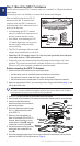
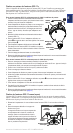
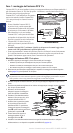
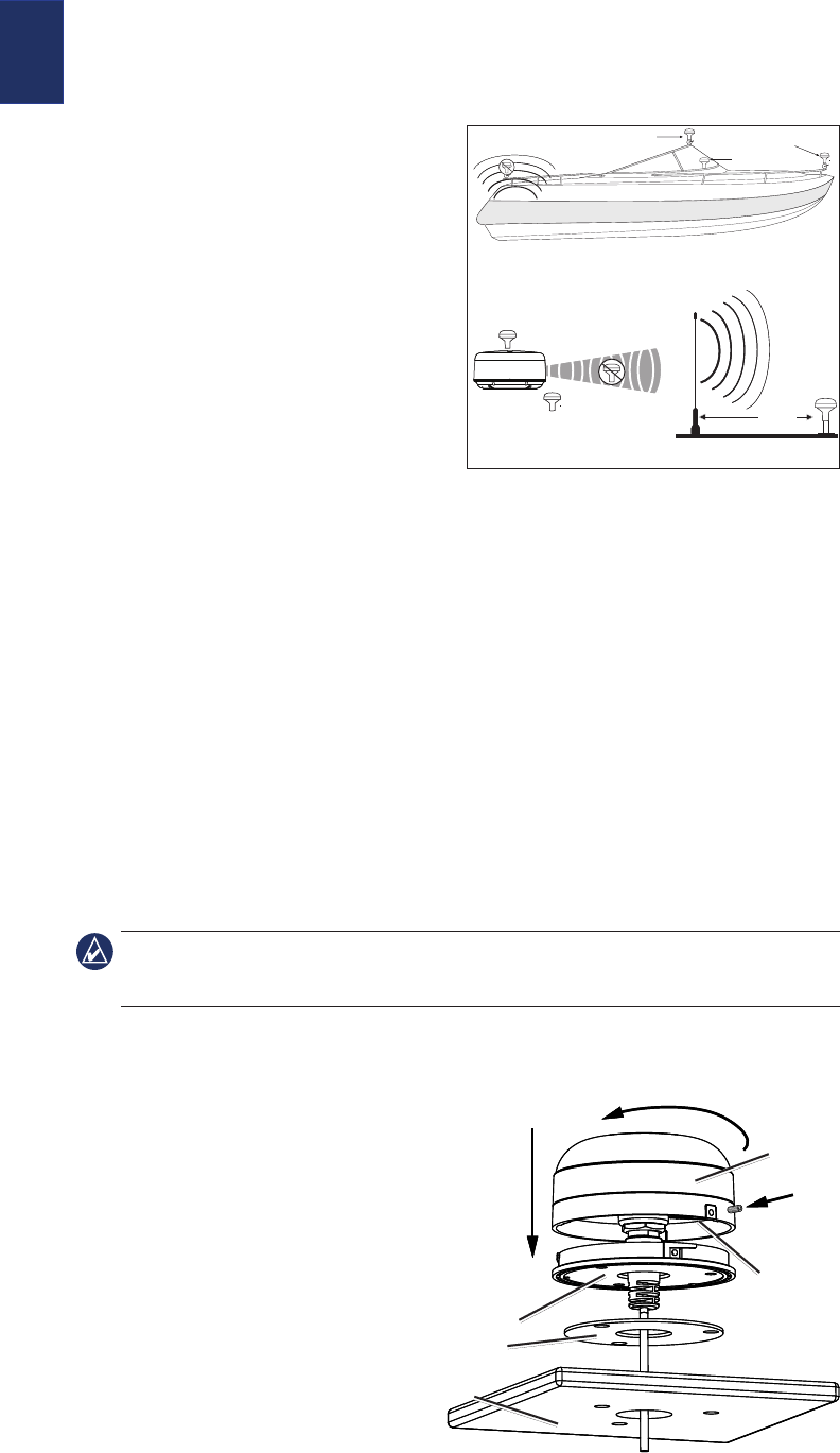
Select a suitable location for the GPS 17x
antenna on your boat. To ensure the best
reception, mount the GPS 17x antenna in a
location that has a clear, unobstructed view of
the sky in all directions.
Avoid mounting the GPS 17x antenna
where it is shaded by the superstructure of
the boat, a radome antenna, or mast.
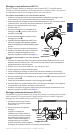
On a sailboat, avoid mounting the GPS
17x antenna high on the mast, to prevent
inaccurate speed readings caused by
excessive heeling.
The GPS 17x antenna provides more-stable
readings when located nearer to water level.
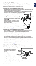
Temporarily secure the antenna in the preferred mounting location and test it for correct
operation. If you experience interference with other electronics, try a different location.
When you verify correct operation, permanently mount the antenna.
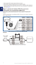
Surface-mounting the GPS 17x Antenna
1. Use the surface-mount bracket as your mounting template
Use the center punch to mark the three screw locations on the surface.
Use a pencil to trace the cable hole in the center of the bracket.
Set the surface-mount bracket aside. Do not drill through the surface-mount bracket.
2. Select the appropriate drill bit for your mounting surface using the drill bit table (page 1), and
drill the three pilot holes.
If you are mounting the GPS 17x on berglass, it is recommended to use a countersink
bit to drill a clearance counterbore through the top gelcoat layer (but no deeper). This will help to
avoid cracking in the gelcoat layer when the screws are tightened.
3. Use a 1 in. (25 mm) hole saw to cut the cable hole in the center.
4. Place the seal pad on the bottom of the surface-mount bracket. Make sure that the screw holes align.
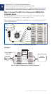
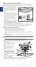
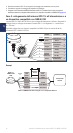
5. Use the included M4 screws to
attach the surface-mount bracket to
the mounting surface.
6. Route the power/data cable through
the 1 in. cable hole and connect it
to the GPS 17x.
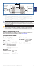
7. Make sure the large gasket is in
place on the bottom of the GPS 17x
antenna, place the antenna on the
surface-mount bracket ➊, and twist
it clockwise to lock it in place ➋.
8. Secure the antenna to the mounting
bracket with the included M3 set
screw ➌.
9. Route the power/data cable away from sources of electronic interference, and connect it to
power and a NMEA 0183-compliant device. (Page 4)
•
•
•
•
•
•
•
•
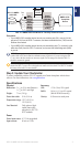
SS BARNETT
Radar
VHF Radio Antenna
3 ft.
(1 m)
Above - best
Below - OK
EMI (Electromagnetic Interference)
from engine components
Best
Better
Good
EMI
GPS 17x Placement Considerations
SS BARNETT
Radar
VHF Radio Antenna
3 ft.
(1 m)
Above - best
Below - OK
EMI (Electromagnetic Interference)
from engine components
Best
Better
Good
EMI
GPS 17x Placement Considerations
GPS 17x
antenna
Surface-mount
bracket
Seal pad
Mounting
surface
➊
➋
➌
Rubber
gasket
GPS 17x
antenna
Surface-mount
bracket
Seal pad
Mounting
surface
➊
➋
➌
Rubber
gasket