


AXIS Q2901-E Temperature Alarm Camera
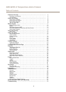
Hardware Overview
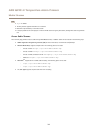
Hardware Overview
4
5
6
3
2
1
7
8
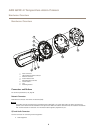
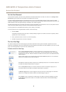
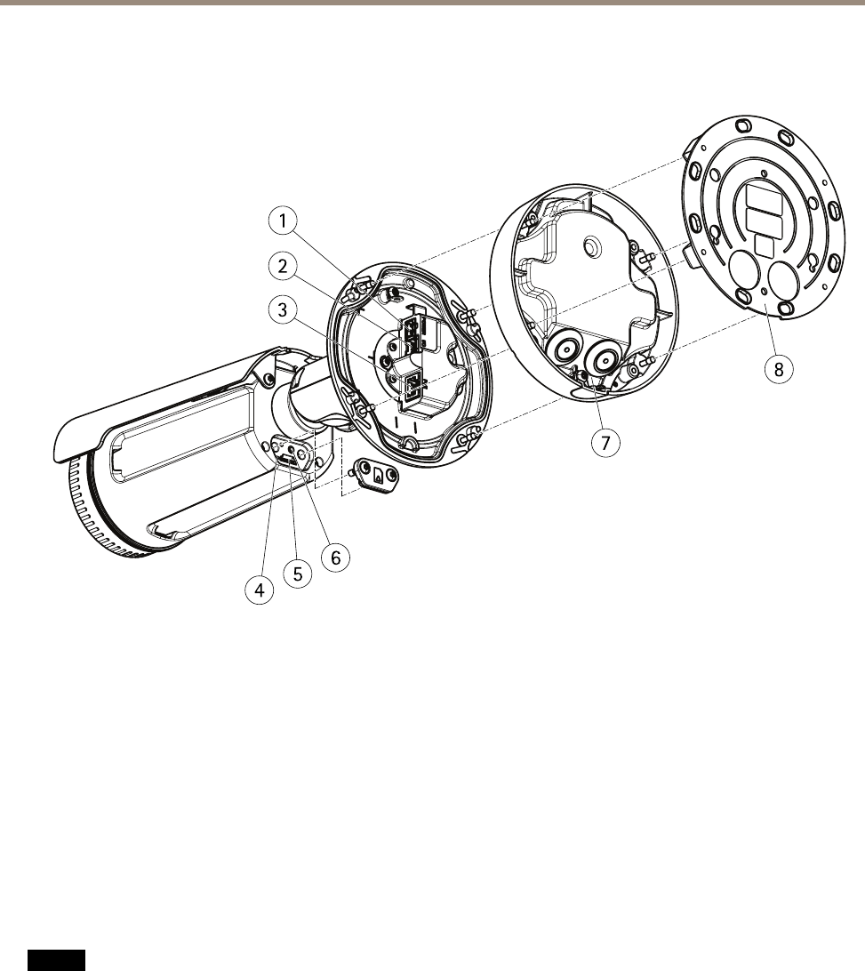
1
Power connector
2
I/O and audio terminal connector
3
Network connector
4
Status indicator LED
5
MicroSD memory card slot
6
Control button
7
Foot
8
Mounting bracket
Connectors and Buttons
For technical specications, see page 63.
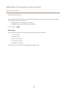
Network Connector
RJ45 Ethernet connector with Power over Ethernet (PoE).
NONO
NO
TICETICE
TICE
The product shall be connected using a shielded network cable (STP) or an optical ber cable. All cables connecting the
product to the network shall be intended for their specic use. Make sure that the network devices are installed in accordance
with the manufacturer’s instructions. For information about regulatory requirements, see .
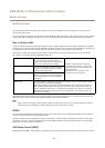
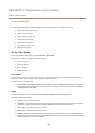
I/O and Audio Connector
Terminal connector for connecting external equipment:
• Audio equipment
6