


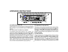

cr LOCAL/DISTANT (LOC) SELECTOR
This feature is used to select the strength of the signals at
which the radio will stop during Automatic Seek Tuning. Press-
ing and holding this button will select the Local setting (LO-
CAL will appear on the display panel) and only strong (local)
stations will be received. Pressing the button again will select
the normal Distant setting (Dx will appear on the display panel).
The radio will stop at a wider range of signals, including weaker
(more distant) stations.
cs MODE SELECTOR (MODE)
This button is used to select the radio, or the playback mode for the
CD player or remote CD changer (if installed). Each press of the
button will select a different mode as indicated on the display
panel.
During CD player operation, this button may be used to change
to radio or remote CD changer mode ("CDC AUX") without ejecting
the disc (the CDP indication will remain on the display panel to
show that a disc is still loaded in the unit). Press the button again to
return to integral CD player mode and resume play of the disc from
the point at which it was stopped.
ct & cu DISC SELECT (D.UP & D.DN)
These buttons are used to increase or decrease selection of a
desired disc for play in the remote CD changer. To advance to a
higher number disc, press the D.UP button ct. To return to a
lower number disc, press the D.DN button cu. The number of the
disc in play will be shown on the display panel.
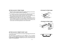
dl FRONT PANEL RELEASE BUTTON
This button is used to release the mechanism that holds the front
panel to the chassis. To detach the front panel, press the button
so that the left side of the panel is released. Grasp the released side
and pull it off of the chassis.
To re-attach the panel, position the right side of the panel in place
first and then press the left side of the panel in until the mechanism
locks it into place.
dm THEFT-DETERRENT LED
The theft-deterrent Light Emitting Diode (LED) is located behind the
front panel and is accessible when the front panel is removed. The
flashing light serves as a visual warning to the would-be thief that
the unit has been disabled by removal of the front panel.
dn RESET BUTTON
A RESET button is located on the front of the chassis (front panel
must be removed to access the button). The RESET circuitry is
provided to protect the microprocessor circuitry and should only
be activated under the following circumstances as it will erase the
time and pre-set memories:
1. Upon initial installation after all wiring is completed.
2. After the position of the frequency step switch on the bottom
of the chassis has been changed.
3. If there is a malfunction of any of the switches on the unit,
pressing the RESET button may clear the system and return
to normal operation.
-8-