


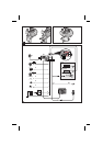


Speedometer signal (ISO connector A):
Depending on the type of speedometer signal, either the digital (A1) or the analogue
(A3) input must be selected. Check speedometer signal using an oscilloscope if
necessary.
A
Never tap the speedometer signal from the ABS control!
Digital (standard):
Connect the black/white cable A1 from cable harness to the tapping position of the
speedometer signal. Location and connection details can be found in the vehicle
specific information sheets (available as CD ROM).
Note: Many cars are supplied with the speedometer signal on one of the car radio
connectors. Ask your car dealer for more information or call our hotline.
Analogue (for retrofitted speedometer senders and magnetic sensors):
Connect the short black/white A3 cable (directly at ISO chamber A connector) of the
wiring harness to the output of the speedometer sensor or the magnetic sensor.
Further signals (ISO connector A):
1. Connect the white/yellow cable (A2) to a suitable connecting point of the back up
lights (positive pole of the reversing lamp).
2. Connect the grey cable (A6) to a suitable connecting point of the low beam (do not
connect to dashboard illumination!).
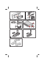
Connecting system components (ISO connector B):
Remote control holder
Connect the plug of the remote control cable to the Mini-DIN socket on the signal
cable harness.
Loudspeaker (accessory):
Connect the loudspeaker (ML 5000) with the 3.5 mm jack to the 3.5 mm plug of the
signal cable harness.
Multimedia extension (ISO connector C3):
A Multimedia Center can additionally be connected to the navigation computer. For
connection details see “Mounting the navigation computer”.
Reproduction of voice messages through vehicle speakers
For reproduction of the guidance messages by the left front speaker of the vehicle you
can connect an adaptor cable MA 1300 (optional) between the loudspeaker connector
and the audio output of the navigation computer.
5