


NEW VISION SURROUND SYSTEM
Contents of Carton:
2 each 2-way Matching Satellites , Shielded
1 each 2-way Center Channel, Shielded
1 each Subwoofer
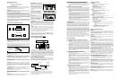
CENTER AND SATELLITE SPEAKERS Your three surround speakers consist of 2
matching Satellites and a Center Channel Speaker. The Satellites have a vertical
orientation while the Center Channel has a horizontal orientation.
SUBWOOFER Your Subwoofer delivers powerful, deep bass sound output for a
natural, life-like sonic experience. Please follow the directions in this manual to
achieve the best performance from your system.
HOW TO PLACE YOUR SYSTEM COMPONENTS Locate the Center Channel on top of
CONNECTING THE SURROUND SPEAKERS Your Receiver will have clearly marked
terminals for connecting the Satellite and Center Channel Speakers. The most common
type of connection is spring loaded. Press down on the tab and insert the stripped wire
tips into the opening.
IMPORTANT: Always connect the red (+) terminal on the Receiver to the red (+)
terminal on the corresponding Speaker i.e. Front Left. Connect the corresponding black
(-) terminal on the Receiver to the black (-) terminal on the same speaker. Continue until
all of the speakers have been connected in this manner.
SUBWOOFER CONTROLS & CONNECTIONS
POWER CORD Plug the power cord into an ACwall outlet or other AC outlet
capable of supplying at least 400 Watts.
POWER SWITCH Turns the AC supply completely OFF or ON or sets the Subwoofer to AUTO
ON operation. In AUTO ON, the Subwoofer is in standby mode until it detects an audio
signal input, then the Subwoofer turns on automatically. A few minutes after audio
input signals cease, the Subwoofer automatically returns to standby mode.
POWER INDICATOR LED This LED is RED when the AC power switch is OFF. It
glows red when the Subwoofer is in standby mode and green when the Subwoofer is
on.
FUSE 250V 2A This fuse protects against internal and external faults. If the POWER
switch is ON and the power indicator LED is unlit, unplug the power cord from the AC
and the back of the amplifier, then pry up the rectangular fuse holder and check the
fuse. IMPORTANT If the fuse is blown, replace it only with a fuse of the same type and
current rating.
L ,R SPEAKER OUT & IN - See Connection Option 1 These terminals are for making
connections using speaker wire. If you use this option, do not use Option 2.
LINE IN & LINE OUT - See Connection Option 2 These are for connections using audio
cables. If you use this option, do not use Option 1.
LOW PASS FREQUENCY CONTROL Adjusts the upper frequency limit for audio sig-
nals going to the Subwoofer amplifier. This control helps you adjust the system’s tonal
balance.
LEVEL CONTROL Balances the loudness of the Subwoofer relative to the Front
speakers and compensates for room effects on the Subwoofer’s output.
PHASE SWITCH The Phase Switch
controls the phase of the Subwoofer’s
output relative to the front speakers. Listen
carefully to the sound quality while
playing a CD with low bass. Select the
position of the switch that produces the
fullest deep bass without boominess. You
may need to readjust the Level and Low
Pass Frequency controls after setting the
Phase Switch.
CONNECTING YOU SUBWOOFER
IMPORTANT: When you make connections.
make sure that the power switches of all
components, including the Subwoofer, are
OFF.
AUDIO CABLES If you are connecting the
Subwoofer into a system made up of
separate components (preamp & power
amps), you will need audio cables long
enough to reach the Subwoofer from the
preamplifier and the power amplifier.
SPEAKER WIRE Typical speaker wire has a pair of separate conductors with
insulating jackets that are molded together. We recommend that you use 16-gauge
speaker wire for hooking your Receiver to your Front speakers. To make
connections to the Subwoofer in parallel with the Front speakers easier, the
speaker wire connecting the Receiver to the Subwoofer can be smaller (higher gauge
number), since the Subwoofer does not draw large amounts of power through these
wires.
POLARITY All speakers in a system must be connected with the same polarity.
Speaker wire is marked for polarity so that you can identify which wire in the pair is
which. Polarity is shown by a color strip on the insulation, by ridges molded into the
insulation, or by the colors of the wires - one copper and one silver.
Strip the insulation from speaker wire ends to reveal the bare conductors before
connecting to Receiver, Subwoofer or Speaker terminals.
IMPORTANT Always connect the red + terminal on the Receiver to the red +
terminal on the Subwoofer, and the black - terminal on the Receiver to the black -
terminal on the Subwoofer. The same is true for hooking the Receiver outputs to the
Front speakers: red + to red +, and black- to black-.
IMPORTANT USE OPTION 1 OR OPTION 2, NOT BOTH.
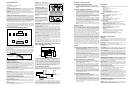
OPTION 1 – CONNECTION WITH SPEAKER WIRE
Connect speaker wires from the Receiver’s front left and right speaker outputs to the
Subwoofer’s Speaker Level-In connections. Connect left channel to left input and right
channel to right input. You have the option of connecting your main speakers to the
speaker B outputs on your Receiver, if it is so equipped or you also have the option of
connecting your main speakers using the connections on the Subwoofer. This will pass
the audio signal to your main speakers, except the low bass which will be produced by
your Subwoofer. To use this connection option, connect your main speakers to the right
and left outputs on the Subwoofer (see illustration 1). Be sure you take care to main-
tain proper signal polarity, red to red and black to black.
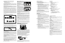
OPTION 2 – CONNECTION WITH AUDIO CABLE
Connect a pair of audio cables from the preamp’s output jacks to the subwoofer’s LINE
IN jacks. Connect left channel to left to left and right channel to right. Connect a pair
of audio cables from the subwoofer’s LINEOUT jacks to the power amplifier’s input
jacks. Connect left channel to left and right channel to right.
If your preamp receiver or processor has a subwoofer or mono output jack that is
controlled by the master volume control, use a single audio cable to connect that
output to the subwoofer’s Line-In jack. No audio cables from the subwoofer’s Line-
Out jacks are needed in this set-up.
Television
Center
Tower
(Sold Seperately)
Tower
(Sold Seperately)
Subwoofer
Satellite Satellite
Primary Listening
SUBWOOFER
LEFT
SPEAKER
RIGHT
SPEAKER
RECEIVER
Speaker Outputs
Speaker Level
Out
In
Home Theater Surround System Diagram
PRE-AMPLIFIER
SUBWOOFER
POWER AMPLIFIER
LEFT SPEAKER
RIGHT SPEAKER
or under the television or monitor. If your New Vision 3.1 system is going to be used with
either the matching New Vision Towers or an existing pair of speakers as the fronts, then
the satellites should be located behind you with one to the right and the other to the left
of your primary listening location. Ideally the tweeters of all speakers should be as close
to level with your ears as possible due to the increased directionality of higher frequencies.
If you are using your New Vision 3.1 system as a "front stage" then place the satellites
with one on each side of your television or monitor.
Your subwoofer should sit on the floor close to a wall, moving it closer to a corner will
increase its bass, but in some cases may cause it to be excessively "boomy". Some
experimentation with placement, phase, and crossover adjustment will be necessary for
the best overall sound in your specific room.
+ TO RED TERMINAL
(color stripe ridges
or copper)
3/8” (9mm)
-TO BLACK TERMINAL
(plain or silver)
BARE WIRE
,
110-120VAC
200W
60Hz
CAUTION
AVIS:RISQUEDECHOCELECTRIQUE-NEPASOUVRIR.
REFERSERVICINGTOQUALIFIEDSERVICEPERSONNEL
COVER(ORBACK).NOUSER-SERVICEABLEPARTSINSIDE
TOREDUCETHERISKOFELECTRICSHOCK,DONOTREMOVE
CAUTION:
NOTSUITABLEFORIN-WALLMOUNTING
WARNING:SHOCKHAZARD-DONOTOPEN.
RISKOFELECTRICALSHOCK
DONOTOPEN
2AL250V
CROSSOVER SUBWOOFER LINE LEVEL
FREQUENCY LEVEL LINEIN LINEOUT
0
PHASE
180
MODE
AUTO
POWER
L
R
L
R
OFF ON
SPEAKERLEVELOUT SPEAKERLEVEL IN
MODEL:NEWVISIONSUB
SERIAL NO.:
R RL L
AJUSTE Y UTILIZACIÓN DEL SUB-ALTAVOZ PARA GRAVES (SUBWOOFER)
CONFIGURACIÓN INICIAL DE LOS CONTROLES DEL SUBWOOFER
• Colocar el control de FRECUENCIA DE PASO BAJO en posición central.
• Colocar el control de NIVEL completamente en contra de las agujas del reloj en
MIN. Podrá reajustarse este control una vez que se hayan efectuado otros
ajustes.
CÓMO AJUSTAR LOS CONTROLES DEL SUBWOOFER
• Ejecutar un programa en el sistema. Para efectuar los ajustes que se detallan a
continuación, utilizar el modo de sonido envolvente Dolby ProLogic Normal y
seleccionar una película que tenga una extensa banda de sonido grabada con el
sistema Dolby Surround, o reproducir un CD de música. Ajustar el control de vol-
umen del receptor para obtener un nivel de sonido confortable de los altavoces
del sistema.
• Aumentar el Control de NIVEL del Subwoofer moviendo el dial hacia la derecha,
de forma tal que puedan escucharse bajos profundos. Ajustar el control para
obtener un balance musical natural que tenga un sonido pleno de bajos profun-
dos cuando se esté reproduciendo música.
• Escuchar atentamente las voces graves y, de ser necesario, ajustar el control de
FRECUENCIAS DE PASO BAJO, para que suenen en forma natural. Si se ajusta
la frecuencia a un nivel muy alto se logrará que las voces graves suenen con
mucha resonancia y el bajo alto en música sonará con calidad de "sola nota". Si
se ajusta el control de frecuencia a un nivel muy bajo, las voces graves sonarán
muy "débiles" y a la música le faltará "calidez".
• Efectuar ajustes con más grado de detalle hasta que el programa tenga una cali-
dad de sonido natural y satisfactoria tanto con respecto a voces como a música.
SOPORTE DE MONTAJE
El sistema del altavoz New Vision contiene un sistema del montaje de pared que está dis-
eñado específicamente para los satélites New Vision. El sistema de montaje incluye cuatro
varillas de montaje con plato asegurado, arandelas de compresión y cuñas angulares.
El sistema NO incluye herrajes para fijar los soportes de montaje del pared en el super-
ficie de montaje. Con este sistema, cuando instale el sistema correctamente, el
escuchante puede concentrar los satélites a la ubicación de escucha principal.
Con un satélite en el mano, observe el panel trasero. Las tapas superior y inferior
empuja hacia fuera. La tapa inferior tiene un agujero dentro. Presione una de las aran-
delas de compresión en la abierta. El corte-molde de la arandela tiene que extender en
los dos lados de la tapa. Coloque el extremo libre de varilla de montaje en la arandela
del fondo, tire el satélite y empuje la varilla lentamente. Asegúrese de que no descon-
necte la arandela de la ubicación. Continue a empujar hasta la varilla entra el inserte
dentro la tapa superior. Ahora puede retirar el satélite horizontamente en la varillla
para accesar el plato de montaje y completar la instalación del soporte.
Cuando el plato está fijado al superficie de montaje, puede retirar fácilmente los
satélites a la orientación deseada. La arandela de compresión ayuda mantener el
satélite en la unbicación deseada. Si necesita un ajuste vertical, hay una cuña que está
diseñado para colocación entre el plato y el superficie de montaje.
SOLUCIÓN DE PROBLEMAS
EL LED INDICADOR DE ENERGÍA DEL SUBWOOFER NO SE ENCIENDE
• Controlar que el interruptor de energía del Subwoofer se encuentre en posición
AUTO ON.
• En caso de que el Interruptor de energía esté en posición AUTO ON, controlar
que la toma de corriente AC del Subwoofer este conectada, para asegurarse
que tiene energía. Para corroborar esta condición, puede utilizarse un tester o
un busca polos.
• Si la toma de corriente AC está cargada (o 'viva'), existe un problema en el cable
de alimentación o en el Subwoofer. Desconectar el cable de alimentación de la
toma de corriente AC y controlar el fusible, desenroscando la parte central del
porta fusible. En el caso que el fusible esté quemado, deberá ser reemplazado
solamente con un fusible del mismo tipo y gama de corriente. Si este proced-
imiento no resulta efectivo, llevar el Subwoofer al agente autorizado para su
reparación - DENTRO DEL APARATO NO HAY PIEZAS QUE PUEDEN SER
REPARADAS POR EL USUARIO.
LOS ALTAVOCES FRONTALES NO EMITEN SONIDO ALGUNO.
• Asegurarse que los interruptores de energía del aparato receptor y del
Subwoofer estén en posición ON.
• Controlar al estado del control de volumen, si se encuentra completamente al
mínimo, no habrá sonido.
• Controlar que el selector de entrada del aparato receptor esté conectado a una
fuente activa de señales de audio y que el control "Tape Monitor Loop" no esté
activado.
• Asegurarse que el selector de altavoces del aparato receptor esté seleccionan-
do las terminales [A or B, 1or 2] a las que se ha conectado altavoces frontales.
Si el aparato receptor posee ficha para auriculares, pueden utilizarse auricu-
lares para controlar la salida del receptor.
• Controlar los cables y conexiones que van desde las terminales de salida del
receptor para los altavoces frontales a las terminales SPEAKER-IN del sub-
woofer.
• Intentar retirar el Subwoofer del sistema, dejando los altavoces frontales conec-
tados al aparato receptor. Si aún entonces no hay sonido, llevar el aparato
receptor al agente autorizado para su reparación.
EL SUBWOOFER NO EMITE SONIDO ALGUNO
• En primer lugar, asegurarse que hay sonido por los altavoces frontales y que el
aparato receptor funciona correctamente de la manera que se lo detalla anteri-
ormente.
• Controlar que el CONTROL DE NIVEL de sonido del Subwoofer. Si el dial esta
totalmente girado hacia la izquierda, es probable que no haya sonido.
• El Subwoofer sólo reproduce sonidos graves profundos. Si el programa no tiene
este tipo de sonido, el Subwoofer no emitirá sonido alguno. Ejecutar un progra-
ma que tenga gran variedad de sonidos graves y bajos, como música rock o jazz
o una película de acción.
• Si todo lo demás está bien, llevar el Subwoofer al agente autorizado para su
reparación - DENTRO DEL APARATO NO HAY PIEZAS QUE PUEDEN SER
REPARADAS POR EL USUARIO.
ESPECIFICACIONES TÉCNICAS
Canal Central
Altavoces auxiliares: Duales de 3 pulg. con Tweeter de pulg.
Respuesta de Frecuencia: 90Hz-25kHz ±3dB
Sensibilidad: 87dB
Impedancia Nominal: 4-8 ohms
Accione el Manejo: 50 Vatios RMS/100 Vatios Peak
Terminación: Aluminum anodizado
Dimensiones: 3
13
/16 H x 9
1
/4 W x 5
3
/8 D de pulg.
Satélites
Altavoces Auxiliares: Woofer de 3 pulg con Tweeter de
1
/2 pulg.
Respuesta de Frecuencia: 90Hz-25kHz ±3dB
Sensibilidad: 87dB
Impedancia Nominal: 4-8 ohms
Accione el Manejo: 50 Vatios RMS/100 Vatios Peak
Terminación: Aluminum anodizado
Dimensiones: 8
3
/4 H x 3
13
/16 W x 5
1
/2 D de pulg.
Subwoofer
Woofer 8" con diseño horizontal de emisión de sonido frontal
Diseño con ranuras, puerto ajustado a alto.
Respuesta de Frecuencia: 35 Hz a 180 Hz
Amplificación: Potencia de salida: 100 Watts RMS en 4 Ohms con limitador de
protección conectado.
Distorsión armónica total: 10% @ 100 Watts output
Coeficiente Señal-Ruido: = 98 dB
Punto de cruce variable: 40-180Hz
Características especiales:
2 pares de bornes de conexión dorados de cinco vías para entradas de
alto nivel
2 pares de bornes de conexión dorados de cinco vías para salidas de
alto nivel
1 entrada RCA para entrada de bajo nivel y 1 para salida
Terminación: Laminadas en vinyle con acentos del aluminio
Dimensiones: 19 (H) x 9
1
/4 (W) x 16 (D) de pulg.
MEDIDAS DE SEGURIDAD IMPORTANTES
ATENCIÓN:
Leer las instrucciones de operación cuidadosa y completamente antes de operar la
unidad Advent Surround System. Asegurarse que el manual este guardado para referencia
futura. También guardar la factura de compra, ya que puede ser solicitada al momen-
to de ejecutar la garantía de reparación.
LIMPIEZA No utilizar productos de limpieza líquidos o limpiadores en aerosol. Utilizar
un paño seco.
ADITAMENTOS No utilizar aditamentos u otro equipo adicional no recomendado por
Advent ya que esto puede resultar peligroso.
AGUA Y HUMEDAD No utilizar el Sistema de Sonido Envolvente (Surround) Advent cerca
del agua, por ejemplo, cerca de bañeras, piletas para lavado de vajilla o ropa; en
sótanos húmedos, cerca de una pileta de natación o en lugares de características sim-
ilares.
ACCESORIOS No colocar el Sistema de Sonido Envolvente (Surround) Advent sobre car-
ros rodantes, trípodes, soportes o mesas inestables. El producto puede caerse, provo-
cando heridas graves a niños o adultos, y el resultante daño grave para el producto.
Utilizar sólo los carros rodantes, trípodes, soportes o mesas recomendadas por Advent o
vendidas con el Sistema de Sonido Envolvente (Surround) Advent. Cualquier tipo de mon-
taje para los altavoces deberá ser efectuado siguiendo las instrucciones de Advent y debe
utilizarse el accesorio de montaje recomendado exclusivamente por Advent.
INVASION DE OBJETOS Y LIQUIDOS Nunca arrojar objetos de ningún tipo dentro
del producto a través de aberturas, ya que pueden ser puntos de alto voltaje o se puede
ocasionar un corto circuito que puede derivar en fuego o shock eléctrico. Bajo ninguna
circunstancia derramar líquidos sobre el Sistema de Sonido Envolvente (Surround) Advent.
REPARACIÓN Nunca intente reparar la unidad usted mismo. Abrir el aparato o retirar
las cubiertas lo puede someter a exposición peligrosa a voltaje u otros peligros. Dejar
que el trabajo de reparación sea efectuado por personal competente de Advent.
DAÑOS QUE REQUIEREN SERVICIO DE REPARACIÓN Bajo las siguientes circun-
stancias, solicitar el servicio de reparación:
A. Si se ha derramado líquido o si se han introducido objetos en el producto.
B. Si el producto ha sido expuesto a lluvia o agua.
C. Cuando el producto muestra un cambio distintivo en su funcionamiento.
PARTES DE REPUESTO cuando se necesiten partes de repuesto, asegúrese que el
servicio de reparación haya utilizado las partes de repuesto especificadas por Advent o
partes que tengan las mismas características que la parte original. Los reemplazos de
partes no autorizadas pueden resultar el incendio, shock eléctrico u otras circunstan-
cias de peligro.
CONTROL DE SEGURIDAD Una vez concluido el servicio o la reparación de este pro-
ducto, consultar al técnico y pedirle que se realicen los controles de seguridad que
indiquen que el aparato funciona correctamente.
MONTAJE SOBRE PARED O TECHO El Sistema de Sonido Envolvente (Surround) Advent
posee enganches de 1/4 x 20 para montar en pared. El producto solo podrá ser mon-
tado en paredes o techos recomendado por Advent.
CALOR El Advent Surround System debe colocarse lejos de Fuentes de calor, como por
ejemplo estufas, cocinas, salidas de calefacción o otros aparatos (incluyendo amplifi-
cadores) que generen calor.
1.
6.