Start Here
s
Run all speaker wiring (16 gauge is recommended) and control wiring (Cat5)* to the DLA2/4/6.
Be sure to label the wires for easy identification.
s
Place the DLA2/4/6 in the same equipment location as the Receiver/Amplifier.
s
Turn off all power to the Receiver/Amplifier and make sure the DLA2/4/6 power supply is unplugged!
s
Strip approximately 3/8" of insulation from the ends of all speaker and control wiring.
Twist the exposed end of each speaker wire to ensure that no loose strands remain.
* If applicable. Cat5 is used for touch pad and IR receiver wiring.
3/8"
Speaker Wire Cat5 Wire
3/8"
A Stereo Receiver with "A/B"
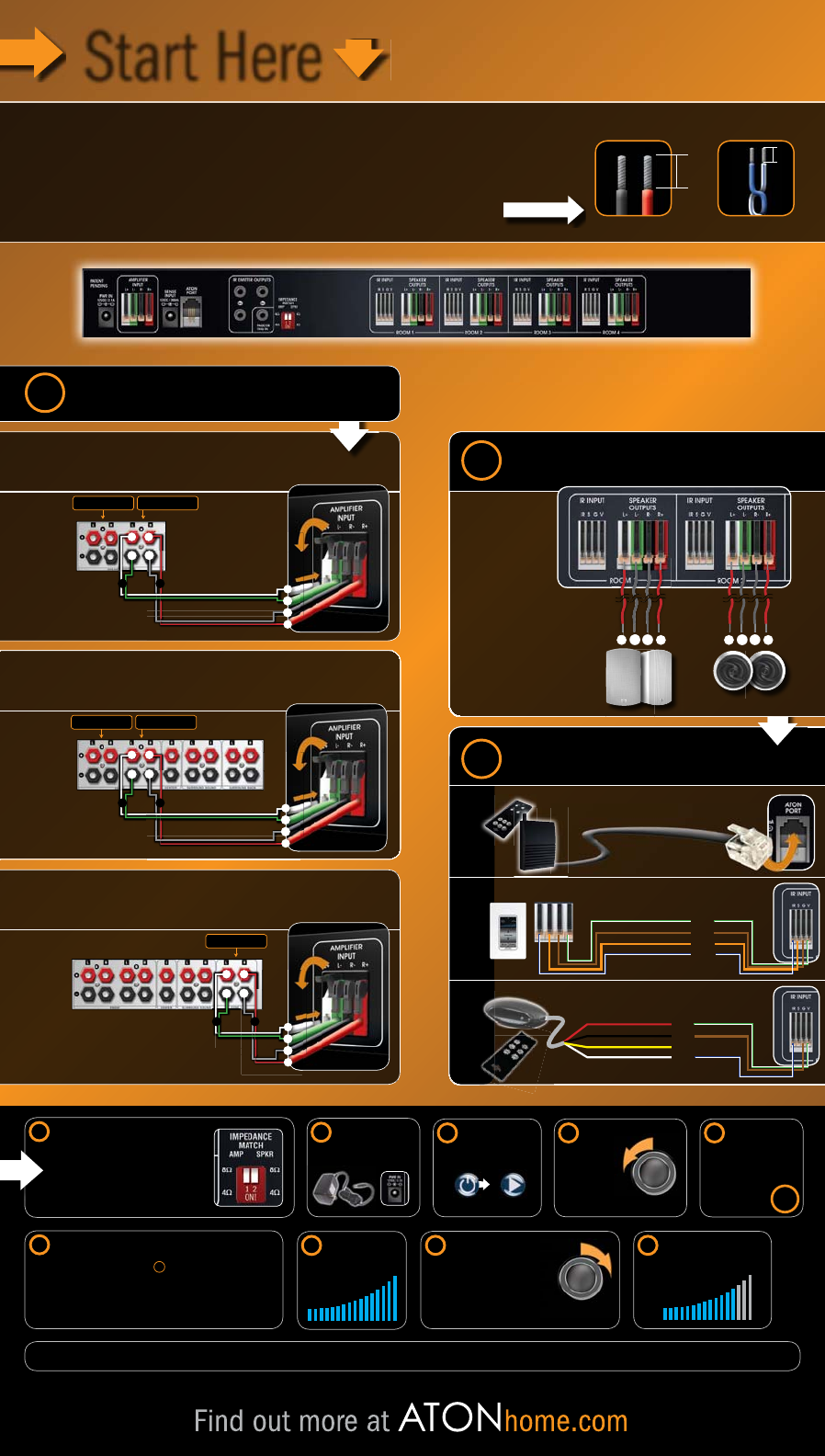
1 Choose Receiver/Amplifier Type
B Home Theater Receiver with "A/B"
2 Connect Speakers
3 Choose Method of Control Optional
RF RECEIVERTOUCH PADSIR RECEIVERS
+
+
–
–
+
–
+
–
C Home Theater Receiver with "Zone 2"
Connect the RF Receiver
to the ATON Port
IR S G V
White/Green (+12V)
Brown (Ground)
Orange (Status)
White/Blue (IR)
Cat5 Wire
Splice to Cat5 Wire
To local speakers To DLA input
Connect
to the
"Zone 2"
speaker
terminals.
To DLA input
NOTE: Refer to your receiver manual for help
activating your "Zone 2" speaker outputs.
+
–
+
–
L
R
+
–
+
–
Connect
to the "B"
speaker
terminals.
To local speakers To DLA input
Red
Black
White
Yellow (Do Not Connect)
White/Green (+12V)
Brown (Ground)
White/Blue (IR)
+
–
+
–
+
–
+
–
L
R
L
R
+
–
+
–
+
–
+
–
Connect
to the "B"
speaker
terminals.
Speaker Wire
Speaker Wire
Speaker Wire
Be sure to connect
the positive speaker
wire to the positive
input of the
speaker and the
negative speaker
wire to the negative
input of the speaker.
RJ11
Set Impedance Dipswitches.
Amplifier Dipswitch:
Set to Receiver/Amplifier Impedance – 8 or 4 Ohms.
(Refer to receiver/amplifier manual for its specific impedance)
Speaker Dipswitch:
Set to Average Speaker Impedance – 8 or 4 Ohms.
(Refer to each speaker manual for its specific impedance)
Plug in the DLA2/4/6
Power Supply.
Adjust the Receiver/
Amplifier
volume
to the
lowest level.
Please consult your owner's manual for additional installation examples, applications and safety instructions.
Turn on the Receiver/
Amplifier and start
audio source (CD
player, radio, etc.).
Power Start
Audio Source
Receiver/Amplifier
Volume Knob
4
5
67
Finally, turn on each room
from the front panel of the
DLA2/4/6 and adjust to a
comfortable listening level.
12
While listening to the room turned
on in the previous step, slowly adjust
the Receiver/Amplifier volume to
a level that is the loudest it can
play in the room without distortion
or clipping. Make a note of the
volume level for future reference.
ned
ust
to
n
tion
.
11
Set the Receiver/
Amplifier to stereo
mode and disable
any surround
sound or DSP
"Sound Fields."
8
Turn on one room
from the front panel
of the DLA2/4/6 and
adjust volume level
to maximum.
10
9
Receiver/Amplifier
Volume Knob
WARNING! Do not connect speakers to the DLA2/4/6 that have an impedance value lower than what is supported
by your receiver/amplifier. In doing so, you run the risk of overheating and damaging both the DLA2/4/6 and your
receiver/amplifier! Consult speaker and receiver/amplifier manuals for their specific impedance ratings.
If using a Receiver with "A/B" speaker outputs:
s3ELECTTHE"SPEAKERSETTINGTOUSEONLY
the speakers connected to the DLA
s3ELECTTHE!"SPEAKERSETTINGTOUSE
both the "A" speakers and those
connected to the DLA
OR
NOTE: When using the "A+B" setting, the receiver volume will need to be adjusted accordingly.
When the DLA2/4/6 is not in use, turn off the "B" speakers and turn on
the "A" speakers for normal stereo/surround sound listening.
!


